
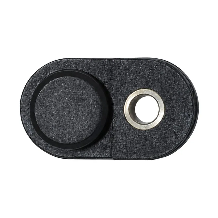
How the process works
A prepared metal insert (a threaded bush, a terminal, a pin, a contact, a stud) is positioned in the mould cavity before the mould closes. Polymer is then injected around it. When the part is ejected, the insert is mechanically locked into the moulded body.
Inserts are commonly loaded by hand into a vertical machine, where gravity helps hold them in position on the lower half of the tool. This is one of the main reasons vertical moulding machines exist alongside horizontal ones.
Why use it
- It removes an assembly operation. No press-fitting, heat-staking or ultrasonic insertion after moulding, and no separate fixture, labour or inspection step for that operation.
- Retention is generally better. Plastic shrinks onto the insert as it cools, gripping it. A well-designed moulded-in insert typically resists pull-out and torque better than one pressed in afterwards.
- It combines materials sensibly. Metal where you need thread strength, conductivity or wear resistance; plastic where you need insulation, light weight and complex geometry.
- Fewer parts to manage. One finished component instead of two items and a joining process.
Where it is commonly used
Threaded bushes in housings that will be assembled and disassembled repeatedly; electrical terminals and contacts moulded into connector bodies and terminal housings; pins and studs providing mounting points; and metal reinforcement in parts that carry load at a specific location.
Several of the insert-moulded components we produce fall into the electrical and connector category, where the insert carries current and the plastic provides insulation and location.
Design rules that decide whether it works
Give the insert something to grip
A smooth cylindrical insert will eventually rotate or pull out. Inserts intended for moulding in are made with knurling, grooves, undercuts, hexagonal sections or flats specifically so the polymer can key into them. Resisting torque and resisting pull-out are two different requirements and may need two different features.
Maintain adequate wall thickness around the insert
Too little plastic around an insert cracks, either immediately from moulding stresses or later in service. The material around the insert also has to accommodate the difference in thermal expansion between metal and polymer, which cycles every time the part heats and cools.
Keep the wall uniform
The usual moulding rules still apply. A thick collar of plastic around an insert is a thick section, and thick sections produce sink marks and voids. Coring and gradual transitions matter here as much as anywhere else.
Locate the insert positively
The tool must hold the insert precisely. If it can shift under injection pressure, position will vary from shot to shot and the melt may flow where it should not. Inserts that must remain clear of plastic, such as a thread bore or a contact face, need a positive shut-off against them in the tool.
Consider preheating
A cold metal insert chills the polymer around it, which can produce poor bonding, weld lines and local stress. Preheating inserts is a common remedy, particularly with semi-crystalline materials and larger metal masses.
Common failure modes
- Insert spins in the body. Insufficient anti-rotation geometry. Flats, knurling or a hexagonal section are needed, not just a groove.
- Insert pulls out under axial load. No undercut or circumferential groove for the plastic to key into.
- Cracking around the insert. Wall too thin, stress concentration at a sharp corner, or thermal cycling the design did not allow for.
- Flash on a functional surface. The tool is not shutting off cleanly against the insert, often because insert tolerance is looser than the tool assumed.
- Inconsistent position. Inadequate location in the tool, or insert dimensional variation exceeding what the tool can accommodate.
Insert dimensional variation is a frequent and under-appreciated source of trouble. The tool shuts off against the insert, so if insert diameter or length varies more than the tool allows, the result is flash, damage or inconsistent retention. Supply the insert drawing with its tolerances as part of the enquiry, and treat incoming insert inspection as part of the quality plan.
Insert moulding compared with overmoulding
The two terms are often used loosely. Insert moulding generally means moulding around a discrete component, most often metal. Overmoulding generally means moulding one polymer over another (a soft grip over a rigid body, for example), where the concern is the bond between two polymers and their chemical compatibility.
The tooling considerations differ. Insert moulding is mainly about locating and sealing against a foreign component; overmoulding is mainly about adhesion between materials and the sequence in which they are moulded.
When to consider an alternative
If volumes are low and the insert is a standard threaded bush, post-moulding installation by heat or ultrasonic insertion may be cheaper overall, because it avoids the cycle-time penalty of manual loading and the tooling complexity of shutting off against the insert. Insert moulding earns its place when retention requirements are demanding, when the insert is non-standard, or when the assembly operation it replaces is itself expensive.
Have an insert-moulded component to produce?
Send the part drawing together with the insert specification and expected volumes, and we will review tooling approach and retention requirements.
Request a Quote View Capabilities