
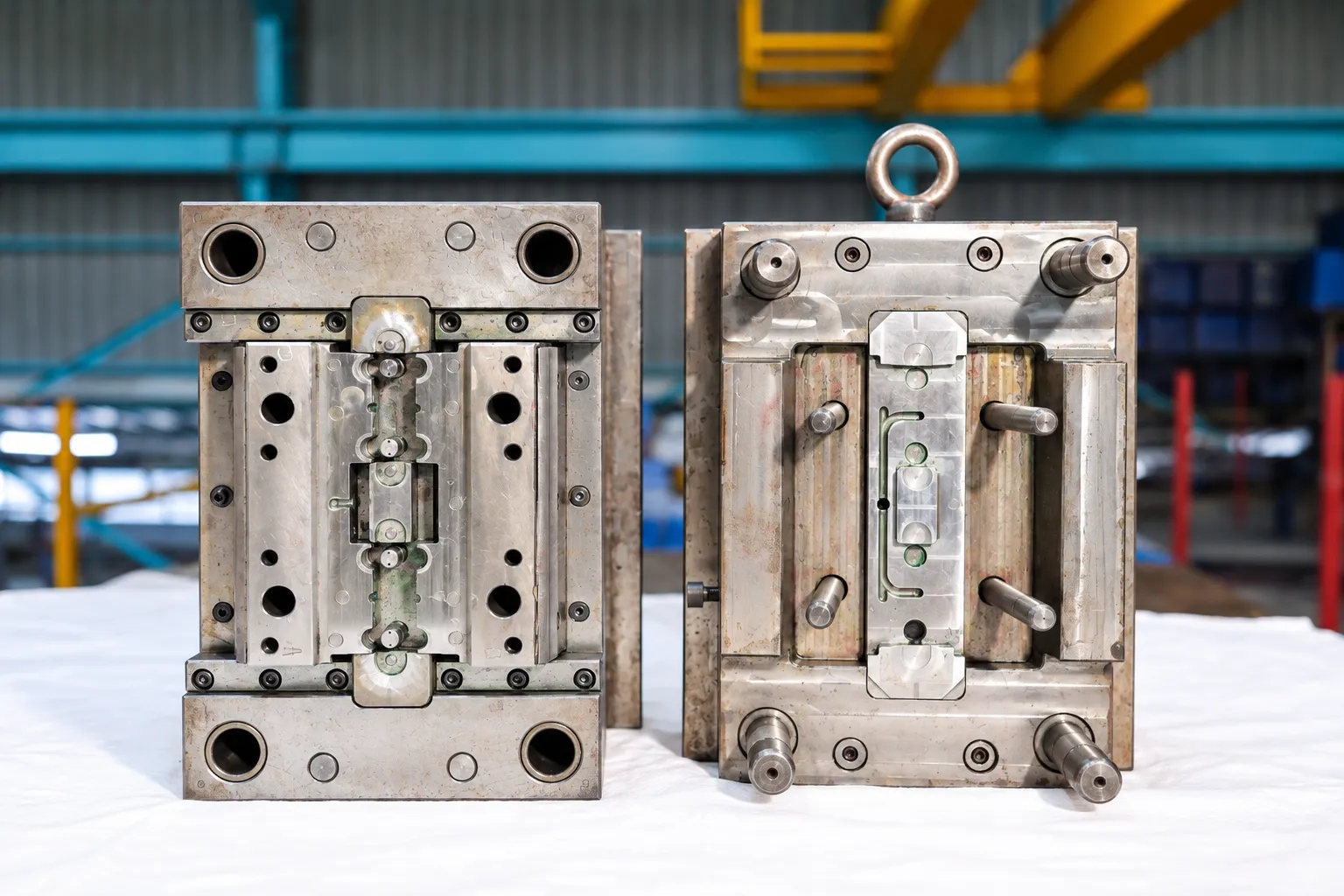
01/Design & engineering
Tool & Mould Design
Injection mould design that starts with the part: feasibility, parting line, gating, cooling and ejection worked out, and checked with mould-flow simulation where it matters, before any steel is cut.
Overview
Good mould design is decided before machining starts
Part quality, cycle time and tool life are largely fixed at the design stage.
We design complete injection moulds (parting lines, gating, cooling, ejection and any sliders or lifters) and validate them through feasibility review and mould-flow simulation. The same team then builds and runs the tool, so design decisions are made with production in mind.
- Part design & analysis
- Design concept development
- Reverse engineering
- Tool feasibility analysis
- Mould-flow simulation
- Parting line analysis
Process
Our mould design process
Inputs
3D model, 2D drawing, material, volumes and finish. From a sample part, we start with reverse engineering.
Part & feasibility review
Draft, wall thickness, ribs, undercuts and tolerances checked; design changes proposed where they help.
Concept & parting line
Parting line, cavity count, gate type and position, and side actions decided.
Mould-flow check
Filling, weld lines, air traps and cooling reviewed in simulation where the part needs it.
Design disciplines
Systems designed into every mould
Injection system
Gate location, balanced runner layouts and hot runner systems where required, for even filling and consistent parts.
Ejection system
Ejector pin positions and ejection design for clean, distortion-free part release cycle after cycle.
Cooling & hydraulics
Cooling layouts for stable mould temperature, and hydraulic design for core pulls and side actions.
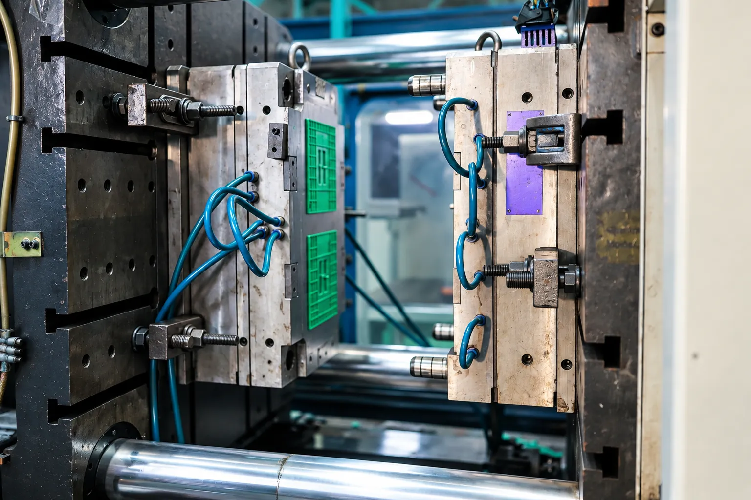
Why it matters
Design choices you will see in every part
- Gate position decides where weld lines and the gate mark fall
- Uniform walls and correct ribs prevent sink marks and voids
- Draft lets the part release without drag marks
- Cooling layout sets cycle time and controls warpage
In the design office
From CAD model to a validated mould
3D mould modelling and mould-flow simulation confirm filling, cooling and ejection on screen before any steel is cut.

Related
Continue exploring
FAQ
Mould design: common questions
What files do you need for mould design?
A 3D model in STEP or IGES format and a 2D drawing with critical dimensions and tolerances. If you only have a sample part or a 2D drawing, we can review it and discuss reverse engineering.
What is mould-flow simulation used for?
It predicts how plastic fills the cavity, helping decide gate position, find likely weld lines, air traps and short shots, and compare cooling layouts before the mould is machined.
Can you design a mould from a sample part?
Yes. We model the part from the sample, agree the critical dimensions with you, and then design the mould.
Will you suggest changes to my part design?
Where a feature will cause sink marks, warpage, ejection problems or an unnecessarily complex tool, we point it out with a suggested change. Nothing is changed without your approval.
Design review
Send your part for a design review
Share the 3D model or drawing. We will review mouldability and propose a mould concept.