
The basic idea
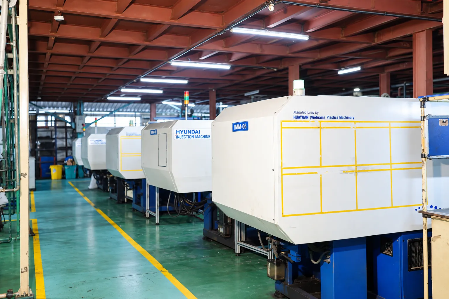
Injection moulding forces molten polymer into a closed steel mould, holds it under pressure while it solidifies, then opens the mould and ejects the finished part. The cycle repeats, typically every fifteen to sixty seconds depending on wall thickness and part size, which is what makes the process economical once volumes justify the tooling.
Everything that matters about quality, cost and lead time follows from two facts: the mould is an expensive, precisely machined steel tool made before the first part exists, and the polymer shrinks as it cools.
The moulding cycle, step by step
- Clamping. The two mould halves are closed and held shut by the machine's clamping force. If clamping force is insufficient for the projected area of the part, the mould will part slightly under injection pressure and produce flash.
- Injection. A reciprocating screw pushes melted polymer through the sprue, runner and gate into the cavity. Fill is usually controlled by velocity rather than pressure.
- Packing and holding. Once the cavity is nearly full, the machine switches to a holding pressure that continues feeding material to compensate for shrinkage. This phase largely determines dimensional consistency and whether sink marks appear.
- Cooling. The part solidifies against the mould surface. Cooling is normally the longest part of the cycle, and the layout of the cooling channels in the mould decides both cycle time and warpage.
- Ejection. The mould opens and ejector pins push the part out. Adequate draft and correctly placed ejectors prevent drag marks and distortion.
Why the mould dominates the economics
A production mould is a machined steel assembly with cavity and core inserts, a runner system, cooling circuits, an ejection system and, where the part geometry demands it, sliders or lifters to form undercuts. It is paid for once, up front, and then amortised over the parts it produces.
This is why unit price falls sharply with volume, and why the first question on any enquiry is annual quantity. A mould that is right for 5,000 parts a year is usually the wrong specification for 500,000.
Cavity count follows the same logic. A single-cavity tool is cheaper to build and easier to correct; a multi-cavity tool costs more but divides the cycle time across several parts. The crossover point depends on volume, part size and the machine the tool will run on.
- Number of cavities
- Undercuts requiring sliders, lifters or unscrewing cores
- Surface finish and texture requirements
- Tolerance on critical features
- Steel selection and expected tool life
- Whether the part needs a hot runner or a cold runner
Design rules that decide whether a part moulds well
Keep wall sections uniform
Thick sections cool more slowly than thin ones. Where the two meet, differential shrinkage produces sink marks on the surface and internal voids. Coring out thick areas and blending transitions gradually is almost always cheaper than trying to fix the symptom with process settings later.
Add draft
Vertical faces need a slight taper so the part releases from the steel. Without draft the part drags on ejection, which shows up as scuffing and can distort thin features. Textured surfaces need more draft than polished ones.
Design ribs properly
Ribs add stiffness without adding wall thickness, but a rib that is too thick where it meets the wall creates exactly the thick section you were trying to avoid. A rib base noticeably thinner than the adjoining wall is the conventional starting point.
Think about where the gate goes
The gate position controls how the cavity fills, where weld lines form, and which direction fibres orient in a filled material. It also leaves a witness mark. Agreeing gate location early, before the mould is cut, avoids expensive rework.
Materials and what they change
Polymer selection affects shrinkage, stiffness, temperature resistance, chemical resistance and cost, and it also changes how the mould must be built. Semi-crystalline materials such as PA66 and POM shrink more than amorphous materials such as ABS and PC, and they shrink differently along and across the flow direction.
Hygroscopic polymers absorb moisture from the air and must be dried before processing. Moulding wet nylon produces surface streaking and a measurable loss of mechanical properties, and no amount of process adjustment recovers it.
At Krishnaraj Enterprises the polymers routinely processed are PA6, PA66, POM, ABS, PC, PBT and PP, on horizontal, vertical and all-electric machines in a 50T to 380T clamping range.
Tolerances: what is realistic
Moulded plastic does not hold tolerance the way machined metal does. Final dimensions depend on shrinkage, which in turn depends on material, wall thickness, holding pressure, mould temperature and cooling time. A dimension across a parting line behaves differently from one contained entirely within a single cavity insert.
The practical approach is to identify the genuinely critical dimensions (the ones that control fit, sealing or assembly) and tolerance those properly, while leaving non-functional dimensions open. A drawing where every dimension carries a tight tolerance usually signals that none of them has been thought about, and it raises cost without improving the part.
When injection moulding is the wrong answer
- Very low volumes. If you need fifty parts, tooling will dominate the cost. Machining from stock or additive manufacturing is usually more sensible.
- Geometry that cannot be released. Some shapes need so many side actions that the tool becomes disproportionately complex. Splitting the design into two moulded parts that are joined afterwards is often cheaper.
- Very large, thick, solid sections. Cooling time scales with the square of wall thickness, so heavy solid parts give poor cycle times and a high risk of voids.
- A design that is still changing. Cutting steel before the design is settled is how tooling budgets get spent twice.
Moving from design to production
A typical sequence runs: design review and feasibility, mould design, mould manufacture, first trial samples, dimensional validation against the drawing, correction if required, and then approval for production. The dimensional check at first-article stage is the point where design intent and manufacturing reality are reconciled, so it is worth agreeing in advance what will be measured and how.
If you are preparing to approach a supplier, the information you send with the enquiry has more effect on quotation accuracy than anything else.
Discussing a moulded component?
Send your part drawings, polymer grade and expected volumes, and our engineering team will review feasibility and come back with a considered quotation.
Request a Quote View Capabilities