
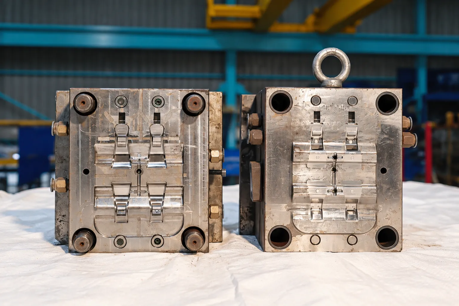
1. Feasibility and design review
Before any steel is ordered, the part geometry is examined for manufacturability. The review looks at wall thickness distribution, draft angles, undercuts, likely gate positions, where weld lines will form, how the part will be ejected and which dimensions are genuinely critical.
This stage produces the most valuable output of the whole project: a list of the part features that will cause difficulty, while changing them is still inexpensive. A design change at review costs an email. The same change after the cavity is cut costs machining time, steel, and often schedule.
Where flow behaviour is uncertain (long flow lengths, thin walls, multiple gates, filled materials), mould-flow simulation is used to predict fill pattern, pressure requirement and likely problem areas before committing to a gating strategy.
2. Mould design
With the part settled, the tool itself is designed. The decisions made here determine nearly everything about how the mould will behave in production:
- Cavity count and layout, balanced against volume and the available machine sizes.
- Parting line: where the mould splits, which dictates where flash risk and witness lines fall.
- Feed system: sprue, runner and gate type and position, or a hot runner where the application justifies it.
- Cooling circuits, which control both cycle time and warpage. This is frequently the difference between a tool that runs well and one that merely works.
- Ejection: pin, sleeve or stripper plate, placed where the part can take the load without distorting.
- Side actions: sliders, lifters or unscrewing mechanisms, wherever geometry cannot be released along the opening direction.
- Venting, so displaced air can escape as the cavity fills.
- Shrinkage compensation: the cavity is deliberately cut oversize by the expected shrinkage of the specified grade.
3. Steel selection
Steel is chosen for the duty. Pre-hardened grades machine readily and suit moderate volumes; through-hardened hot-work grades give better wear resistance and longer life for higher volumes or abrasive filled materials. Glass-filled polymers are abrasive and wear gates and cores noticeably faster than unfilled grades, which is a factor in both steel choice and maintenance planning.
The tool steels we work with are H13, P20, 1.2344 and 1.2738, with hardened tool steel processed up to HRC 60.
4. Machining the mould base and plates
Mould base plates are squared, drilled for guide pillars, bushes and cooling lines, and prepared to receive the cavity and core inserts. Accuracy here sets the foundation: if plates are not square and parallel, no amount of precision in the cavity will produce a tool that shuts off correctly.
5. CNC machining of cavity and core
The forming surfaces are machined on vertical machining centres, roughing first and then finishing with progressively smaller tools to reach the required surface profile. Complex three-dimensional surfaces are cut with ball-nose tools following calculated toolpaths, and the step-over determines how much hand finishing is needed afterwards.
Features that cutters cannot reach (sharp internal corners, deep narrow ribs, fine detail) are left for electrical discharge machining.
6. EDM and wire cutting
Electrical discharge machining removes metal by controlled electrical discharge rather than cutting force, so it can produce sharp internal corners and work hardened steel.
- Sinker EDM uses a shaped copper or graphite electrode, itself machined to the required form, to burn a matching cavity detail. Fine finishing settings produce the surface texture directly.
- Wire EDM cuts through hardened steel with a fine travelling wire, used for insert pockets, punches, and tight-tolerance profiles.
- Small-hole EDM drilling produces deep cooling and ejector holes that conventional drilling cannot achieve accurately.
Electrode manufacture is a significant part of the work: each sinker EDM operation needs its own electrode, and often a roughing electrode plus a finishing one.
7. Grinding and precision finishing
Surface grinding brings plates and inserts to final size and establishes the flatness and parallelism that shut-off faces depend on. Shut-off surfaces that are not truly flat produce flash no matter how well the rest of the tool is made.
8. Fitting, polishing and assembly
The tool is assembled and the two halves are fitted to each other by hand. Shut-off faces are blued and adjusted until contact is even. Sliders and lifters are fitted and their movement checked through the full stroke. Ejector pins are fitted and their travel confirmed.
The forming surfaces are then polished or textured to the specified finish, and the cooling circuits are pressure tested for leaks. Fitting is skilled manual work and is one of the hardest stages to compress in a schedule.
9. First trial and sampling
The tool is mounted in a suitable machine and the first samples are produced. The purpose of the first trial is diagnostic rather than productive: does the tool fill, does it eject cleanly, does it shut off without flash, and where does the part sit dimensionally against the drawing?
Samples are then measured against the 2D drawing and the CAD model. Dimensional mapping at this point is the formal reconciliation between design intent and manufacturing reality, and it is what our first-article inspection stage is for.
10. Correction and approval
Almost every tool needs some adjustment after first sampling. Steel can be removed but adding it back is difficult, so cavities are deliberately cut on the safe side where a dimension is uncertain, leaving material that can be taken away once the actual shrinkage of the specified material is known.
This is why planning for at least one correction cycle is realistic rather than pessimistic. Once samples are approved, the tool moves to production and the process parameters that produced the approved samples become the documented setup.
- Design changes arriving after machining has started
- Material grade changed late, altering shrinkage compensation
- Cosmetic requirements not agreed until first samples are seen
- Insert specifications supplied late or revised
- More correction cycles than planned, usually from an unresolved design issue
Most of these trace back to information that was not settled before steel was cut.
Our tool and die manufacturing and tool and mould design pages set out the equipment and workflow behind each of these stages.
Need a new mould, or a tool corrected?
Send part geometry, expected volumes and the polymer grade, and we will review the tooling approach, cavity layout and likely lead time.
Request a Quote View Capabilities